Fluid Power Lab
Resources
Please visit the http://www.theopeneducator.com/fluid-power for video demonstrations on all topics covered in the AET 334 Fluid Power courses.
The Laboratory is designed to provide hands-on experience and practical applications in fluid power systems. Students perform lab work on measuring instruments, venturi, orifice, Pitot tube, pressure gauge, actuators, pumps, motors, cylinders, and a software to simulate any fluid-power systems.
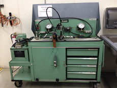
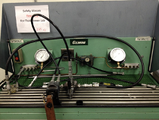
The Fluid Power Laboratory located in Room 101 at Nelson Hall, is used by both the Automotive Engineering Technology and Manufacturing Engineering Technology Programs. As a fundamental component of the AET 334 Fluid Power course, open lab exercises are conducted through the semester of the course. These lab exercises are designed to provide hands-on experience in the fundamental principles of fluid power, along with a practical working knowledge of the components used in designing, installing, and operating hydraulic and pneumatic fluid power systems.
The laboratory allows students to achieve core competences in designing hydraulic and pneumatic systems and solving important engineering problems. Students learn important new technology trends by modeling, simulating, testing, and validating prototypes that support fluid power systems applications.
Students engage in hands-on projects using an Educational Fluid Power Bench and Automation Studio Software to design and analyze the hydraulic and/or pneumatic circuit, which enhances their understanding of the functionality of all components within the fluid power system.
 .
. 
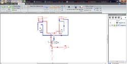
Students can develop and simulate the fluid power systems including pumps/compressors, cylinders/actuators, motors, valves, venturi, orifice, Pitot tube, and other components. They construct studies using Automation Studio Software and explore event–driven simulation capabilities and offline performance for fluid power system integration.
Students conduct measurements such as pressure, flow rate, power, and torque to understand how these parameters change throughout both hydraulic and pneumatic systems. This compliments concepts covered in the classroom regarding operation of components (pumps, motors, cylinders, actuators, connections, fittings) and system design considerations including component interactions and efficiency. Students also gets hands-on experience in measuring instruments, including orifice, venture, Pitot tube, pressure gauge, flow meters, and many more.
An example Lab using Automation Studio.
Lab Assignments and Associated Learning Outcomes
After successfully completing this introductory laboratory, students must be able to demonstrate the following.
- Importance of safety and protective gear.
- Connecting fluid equipment for testing.
- Measure pressure.
- Measure flow rate using a flow meter and manually.
- Connect a four way directional valve.
- Connect a hydraulic cylinder and a four way directional valve.
- Working principle of a hydraulic cylinder and the directional valve.
- Connect a hydraulic motor and a four way directional valve.
- Working principle of a hydraulic motor and the directional valve.
After successfully completing this laboratory on work, energy, hydraulic horsepower, mechanical horsepower, and efficiency, students must be able to demonstrate the following using a hydraulic cylinder with varying loads:
- Measure work & energy.
- Measure hydraulic horsepower.
- Measure mechanical horsepower.
- Measure efficiency.
- Hydraulic systems are highly efficient (can reach up to 95-98%).
- You must include an appropriate reasoning for unexpected values for efficiency.
- Explain the difference between the efficiency and percentage of power conversion.
- Interpret the results from the experiment.
After successfully completing this laboratory on work, energy, hydraulic horsepower, mechanical horsepower, and efficiency, students must be able to demonstrate the following using a hydraulic motor with varying loads:
- Measure work & energy.
- Measure load operating spring loaded scale.
- Measure torque.
- Measure motor speed operating a tachometer.
- Measure hydraulic horsepower.
- Measure mechanical horsepower.
- Measure efficiency.
- Hydraulic systems are highly efficient (can reach up to 95-98%). You must include an appropriate reasoning for unexpected values for efficiency.
- Examine the findings by comparing and contrasting the normal and abnormal.
- Explanation must be needed for unexpected/expected values.
- Distinguish the motor characteristics by plotting characteristic curves, including
- pressure vs. efficiency
- speed vs efficiency
After successfully completing this laboratory on the application of the Bernoulli’s law, students must be able to demonstrate the followings:
- Calculation of velocity in a hydraulic system.
- Calculation of Reynolds number.
- Determination of flow types (laminar, transition, or turbulent).
- Application of Bernoulli’s Law.
- Application of Darcy’s Equation.
- Application of Hagen-Poiseulli Equation.
- Calculation of frictional losses in a hydraulic system.
- Theoretical loss
- Actual loss
After successfully completing this laboratory onvolving work, energy, pneumatic horsepower, mechanical horsepower, and efficiency, students must be able to demonstrate the following. Using a pneumatic cylinder with varying loads:
- Measure work & energy.
- Measure pneumatic horsepower.
- Measure mechanical horsepower.
- Measure efficiency.
- Interpret the findings/calculations, especially for unexpected values.
- Explain the difference between the efficiency and percentage of power conversion.
- Interpret the results from the experiment.
After successfully completing this laboratory on measuring instruments, students must be able to demonstrate the following.
- Measure pressure using a manometer
- Measure flow rate using an orifice meter.
- Measure flow rate using a venturi meter.
- Measure velocity and flow rate using a Pitot tube (or pitot static tube).
- Use of flow control valves, including a three-position four-way directional valve and two-position four-way directional valves, check valves, and flow control valves.
After successfully completing this laboratory on the Automation Studio Software, students must be able to simulate any fluid power circuits in hydraulic and pneumatic systems. A few examples of circuits include.
- Drill-and-clamp cylinder
- Regenerative
- Series
- Parallel
- Fail-safe system with over-load protection
- Two-handed safety system
- Automatic cylinder reciprocating system
- Lock cylinder using pilot check valve
- Counter balancing
- Cylinder sequencing
- Pump unloading
- Double pump system
- Air-over-oil
- Speed control
- Meter-in & meter-out flow control