Mechanical Engineering Labs
Instructional and research laboratories at Minnesota State University, Mankato are equipped with the most modern equipment available for undergraduate mechanical engineering programs. This equipment was acquired since the program was initiated in 1986. The Trafton East building, which houses offices and labs of the Mechanical Engineering Department, was built in 1993. A description of several mechanical engineering labs are given below.
Students needing after-hours access to labs, complete the following and submit to our department office, TE 205.
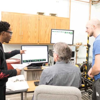
Advanced Design Laboratory
Instructional and research laboratories at Minnesota State University, Mankato are equipped with the most modern equipment available for undergraduate mechanical engineering programs.
Advanced Design Laboratory Collapse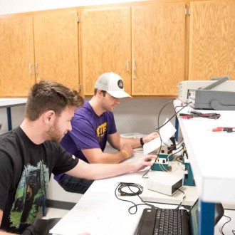
Dynamic Systems Labs
Dynamic Systems experiments are conducted in the Controls Laboratory and the Vibrations Laboratory.
Dynamic Systems Labs CollapseThe Controls Lab is currently dedicated to undergraduate instruction. The equipment in the lab consists of DC motors, power supplies, power amplifiers, operational amplifiers, PID controllers, function generators, and oscilloscopes. In this lab students learn to: characterize systems; design controllers to meet prescribed system specifications; and implement their design and test the overall system for conformance to the prescribed system specifications.
In the Vibration Lab students investigate physical systems. Experiments include: observing frequency response of a system, determining natural frequencies and mode shapes of systems and measuring the effect of a vibration absorber. Motion is caused by motors, shakers or hammers acting on a variety of structures. Measurement of motion is made with piezoelectric accelerometers. Students also use signal processing equipment such as filters and a Fourier analyzer. In addition to the structural vibration capabilities, the laboratory also contains basic sound measurement instruments.
Engine Test Cells Lab
The Engine Test Cells Laboratory has three 6’x12’ Lakeshore cast Iron vibration-isolated T-slotted floor plates which can each accommodate an engine testing setup.
Engine Test Cells Lab CollapseEquipment includes: Stuska 90 horsepower water brake, Stuska 450 horsepower water brake, General Electric 150 horsepower-absorption/ 120 horsepower-motoring DC dynamometer, and a DyneSystems 36 horsepower AC regenerative dynamometer. Some of the engines tested: Garrett GTP 30-67 gas turbine, Yanmar TK 353 diesel engine, Dodge Magnum 3.9 liter V6 gas engine, Kubota 8.3kW running a mixture of diesel and natural gas.
All signals and controls can be performed from a separate control room using National Instruments equipment.
Engineering Projects Lab
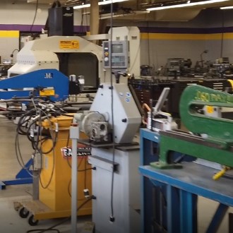
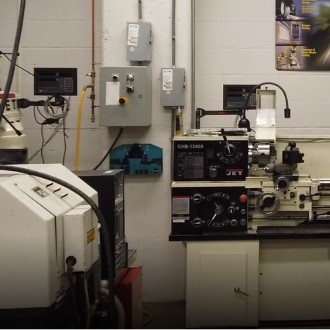
This engineering workshop is a well-equipped machining and fabrication facility which provides a service to the faculty and students of engineering programs.
Engineering Projects Lab CollapseFacilities include lathes, horizontal and vertical milling machines, drills, grinders, saws, shapers, planers, electric and oxy welding, a CNC milling and turning centers, and a multi-axis robot for welding. Manufacture and repair of a wide variety of equipment is undertaken for research, teaching, and general University purposes.
Geometric Dimensioning and Tolerancing Lab
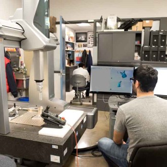
This lab is equipped with a state-of-the-art (as of 2019) Coordinate Measuring Machine(CMM) manufactured by Hexagon Manufacturing Intelligence. Measurement dimensions are 700mm X 1000mm X 660mm. The machine has a accuracy of 1.5 micron (micrometer) over a length of 333mm.
Geometric Dimensioning and Tolerancing Lab CollapseTopics include: Datums, Material condition symbols, Tolerances of Form and profile, Tolerances of orientation and runout, location tolerances, and Virtual condition.
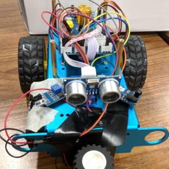
Mechatronics Lab
In the laboratory portion of the Mechatronics class, students progress through a series of exercises that result in the design and fabrication of a mechatronic system that will perform a specified task. The laboratory exercises include the following elements:
Mechatronics Lab Collapse- The design and implementation (programming) of a mechatronic system controller using National Instruments LabVIEW software.
- Interfacing a computer with electromechanical and electronic devices using analog-to-digital and digital-to-analog converters (A/D and D/A) and digital input and output (DIO).
- Fabrication of an 'H-bridge' circuit which in conjunction with a PWM (pulse width modulation) LabVIEW driver will control the speed and direction of a DC motor using two digital outputs from the computer.
- The design and fabrication of the mechanical portions of the system which often include the use of gearmotors, solenoids, sensors, switches and various structural elements.
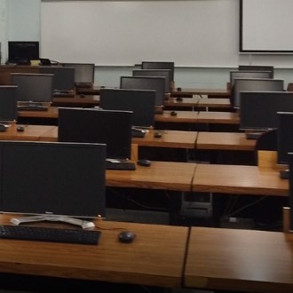
Multipurpose Computer Laboratory
The Multipurpose Computer Lab is equipped with high performance workstations including 24 Dell computers with 3.5 GHz Intel Xeon Processors, 16GB RAM, and 23" LCD Flat Panel Monitors.
Multipurpose Computer Laboratory CollapseThe lab also houses a black and white laser printer, hp LaserJet 4000n. The workstations run Microsoft Office and additional software such as IDEAS, MATLAB, and Visual Analysis
Structural Testing, Material Properties & Manufacturing Operations Lab
The Structural Testing, Material Properties and Manufacturing Operations Laboratory consists of three dedicated areas - over 2,200 square feet. They contain current industrial and educational machines to support engineering education and research. Equipment includes:
Structural Testing, Material Properties & Manufacturing Operations Lab Collapse- MTS computer-controlled uniaxial servohydraulic material testing machine with a 22 Kip load frame. Some of the testing performed is: ultimate tensile strength, material fatigue life, and product fatigue life. The testing machine can handle tensile and compressive testing using a static/ dynamic loading systems.
- Vishay 2300 signal amplifier is one of the data acquisition sysems operated with the MTS machine. It amplifies the output signals from any static or dynamic tests. It consists of 6 full bridge channels and a digital output display. The full bridge channels can be converted into a half or quarter bridge easily.
- Tinius Olsen Tensile Test machine with 60,000 lb. capacity; with x, y output for tensile and compressive tests.
- Monsanto Tensometer bench top tensile test machine with extensometer and heating capacity.
- Vega Enterprise tensile test machine - manual, 20000 lbs.
- Fatigue Dynamics rotating beam fatigue test machine.
- Fatigue Dynamics reciprocating fatigue test machine.
- Charpy impact test machine.
- Lindberg ovens (3) for heat treating.
- Wison Brinell hardness tester.
- Wilson Rockwell hardness tester.
- Alpha Duromatic Rockwell hardness tester.
- Leco Microhardness tester.
- Surface finish machines for metallurgical sample preparation:
- 1 Leco, 2 Buehler — rotary types
- 1 Buehler — belt type
- Bridge model for deflection measurement and calculations
- Buehler abrasive cutter for sample preparation.
- Buehler sample mounting machine.
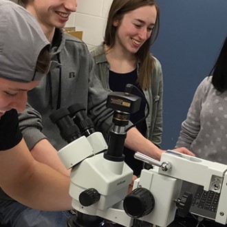
- Microscopes (7) for material inspection.
- Buehler image analyzer for enhanced material inspection.
- Micro measurement Strain Smart 5100.
- Amatrol 11600 Structural System.
Structural Testing and Materials Lab
Various equipment, click to expand.
Structural Testing and Materials Lab CollapseImpact tests of steel–Impact Tester
Objectives:
- Familiarization with the principles involved in impact testing.
- Examination of the effect of temperature change on the impact properties of the material.
- Evaluation of statistical variation in impact energy.
Hardness Evaluation–Rockwell, Brinell Hardness Testers
Objectives:
- Familiarization with the principles involved in hardness testing.
- Determination of hardness with quench rates: Jominy Test.
Structural Deflections–Lab Truss and Weights
Objectives:
- Familiarization with the principles involved in structure testing.
- Analysis of structural deflection due to a point load using energy methods.
Fatigue–22 kip MTS Machine
Objectives:
- Test and calculate fatigue cycle life for non-zero mean loads.
- Observe operation of a state-of-the-art industrial type fatigue test machine.
Tensile Properties–Bench Top Tensile Test Machine
Objectives:
- Familiarization with the principles involved in tensile testing.
- Determination of tensile stress-strain characteristics for a given material.
Fatigue & Buckling–22 kip MTS Machine
Objectives:
- Determine the buckling load for a tensile bar.
- Evaluate the effect on fatigue life from "repairing" a previously yielded part.
Fatigue–Rotating Beam Tester
Objectives:
- To demonstrate how cyclic loading can cause a part failure at a stress less than the material tensile strength.
- To learn the set up procedure for a test machine.
Metrology–Micrometers, Calipers, Gage Blocks, Roughness Comparator
Objectives:
- To become familiar with basic measurements of length.
- To gain insight into the proper selection of measuring equipment.
Manufacturing Operations Lab
Shop safety, practices, orientation. Demo of mill, lathe, welding and other machines. Click to expand.
Manufacturing Operations Lab Collapse
Objective: Become familiar with shop safety procedures and general features of machines tools.
Flexible Manufacturing System Demo. Conveyors, robots, CNC lathe, CNC mill, vision inspection.
Objective: Learn the components, general operating procedures, capabilities and advantages of flexible Manufacturing System — specifically the system at Minnesota State University, Mankato.
CNC Demo. Haas machine center, programming computer
Objective: Observe operation and programming of a CNC machine.
Welding & Brazing. MIG welder, braze equipment, Tinius Olsen Tensile Tester
Objectives:
- Operate a MIG welder to weld steel pieces together in a butt weld and braze a lap joint.
- Learn welding equipment, processes and safety for MIG, TIG and brazing.
- Evaluate statistical nature of welding strength.
Turning, Lathe
Objective:Operate an engine lathe to become familiar with tooling, set up and dimensional control and safety procedures.
Milling — Bridgeport Mill
Objectives:
- Operate a vertical mill to make a specific part.
- Become familiar with set up, tooling, dimensional control and safety procedures.
- Complete a drill and tap operation on the mill.
MECHANICAL ENGINEERING EXPERIMENTATION II, ME 436
The Thermal Fluid Laboratory is mainly used for teaching the practical component of subjects covered in fluid mechanics, thermodynamics, and heat transfer.
Equipment includes:
- Dead weight tester (440 mm x 440 mm x 440 mm)
- Rotating cylinder viscometer
- Falling ball viscometer
- Hydrostatic force test setup
- Air flow measurement bench
- A wind tunnel with 1 ft cross section and maximum velocity of 150 ft/s
- A small calibration wind tunnel
- A Schlieren Optical system
- Smoke and laser sheet flow visualization system
- Centrifugal pump test cell
- Centrifugal fan test cell
- A Pelton turbine
- Jet impact apparatus
- Flow visualization bench
- Precision RTD thermometers
- Thermocouples
- Infrared thermometers
- Humidity sensors
- Precision electronic scales with computer interface
- data acquisition systems
- Compressible flow bench
- Pressure distribution in a converging/diverging nozzle
- Junkers calorimeter
- Bomb calorimeter
- Heating/cooling constant temperature bath/circulators
- Double pipe heat exchanger
- Heat transfer bench w/various heat exchangers configurations
- Internal flow heat transfer apparatus
- Simulated ground loop heat pump system
- Free convection test setup
- Radiation test setup
Pressure Measurement Bench
Students will become acquainted with techniques for the measurement of pressure, including the basic pressure-height relation. A dead weight tester will be used for gage calibration and to examine linearity and hysteresis effects.
Flow Rate Measurement Apparatus
Students will become familiar with techniques used in the measurement of fluid flow rate. Proper calibration of a rotameter and the calculations necessary for a Venturi, flow nozzle, and orifice plate will be determined.
Hydrostatic Force on a Submerged Body Bench
Students will determine the effect of hydrostatic forces acting on submerged surfaces. The hydrostatic force and center of pressure will be experimentally determined and compared to theory.
Fluid Momentum Experimental Bench
Students will become familiar with the measurement of forces developed by fluids in motion. The force produced by a water jet striking a stationary vane will be determined and compared to predictions from fluid mechanics theory.
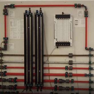
Head Loss in Piping Systems Apparatus
Student will become familiar with the measurement of head loss in piping systems. The friction factor for various pipes and the loss coefficients for fittings and valves will be determined .
Centrifugal Fan Apparatus
Students will study the performance of a centrifugal fan. They will become acquainted with fan characteristics such as specific speed and industry standards for performance characterization.
Centrifugal Pump Apparatus
Students will study the performance of a centrifugal Pump. They will become acquainted with pump characteristics such as head, net positive suction head, and brake horsepower, and how they change with flow rate.
Drag and Lift Measurement Using the Wind Tunnel Lab
Students will acquire experience with wind tunnel testing. Drag coefficients for several objects will be experimentally determined and compared to the tabulated values. Students will investigate the effects of angle of attack on lift and drag coefficients for a NACA airfoil and determine the angle for airfoil stalling.
Heating Value of Fuels Measurement Bench
Students will apply the principles of thermodynamics to the measurement of heating values for fuels. Procedures for both liquid/solid and gaseous fuels will utilized and results compared to standardized values.
Internal Combustion Engine (Diesel) Test Bench
Students will be familiarized with the measurement of common combustion engine factors, including SFC, bmep, nvol , AFR, bhp, and nth . The effect of varying load and throttle settings will be examined and performance data will be gathered.
Nozzle Pressure Distribution Apparatus (Compressible Flow)
Students will be introduced to the phenomena of choking and nozzle pressure distributions for compressible flows. The pressure distribution along the length of a nozzle will be determined. Experimental data will be examined to determine if choked flow occurs and if a shock wave is present in the nozzle.
Vapor Compression Refrigeration Test Bench
Students will become familiar with the operation of an actual refrigeration system. The relationships between key variables in the refrigeration cycle will be explored. A coefficient of performance will be experimentally determined and compared to theoretical values for an ideal cycle.
Heat Transfer Lab
Temperature Measurement Bench
Students will calibrate several thermometers in a water bath to determine linearity and hysteresis. The effect of reference junctions and added resistance on thermocouple circuits, as well as resistance change with temperature for a RTD will be examined. Students will acquaint themselves with the operation of radiation thermometers (pyrometers).
Heat Transfer Lab Collapse
Heat Conduction in Solids Apparatus
Students will be familiarized with measurements of heat transmission in solids and be able to interpret physical phenomena taught in the heat transfer course. The effects of temperature, heat flux, and cross sectional area on thermal conductivity measurements will be examined. Students will experimentally determine conductivity for several samples and compare them to known values.
Free Convection and Lumped Capacitance Apparatus
Students will become familiar with measurements of convective heat transfer and will interpret physical phenomena taught in the heat transfer course. The effects of temperature, heat flux, area, geometry, etc. on heat transfer by natural convection will be examined and the validity of the lumped capacitance method will be explored. Students will be introduced to the use of a data acquisition system.
Convective Heat Transfer (Internal Flow) Test Bench
Students will be familiarized with convective heat transfer for internal flow of a fluid in a tube. Students will be asked to interpret physical phenomena taught in the heat transfer course. The validity and use of known literature correlations for internal flows will be explored.
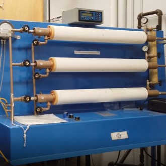
Liquid to Air Heat Transfer (Heat Exchanger Performance) Apparatus
Students will be familiarized with measurements of convective heat transfer between two fluids divided by a rigid wall, as in a heat exchanger. They will interpret physical phenomena taught in the heat transfer course and verify the validity of known literature correlations for heat exchangers.
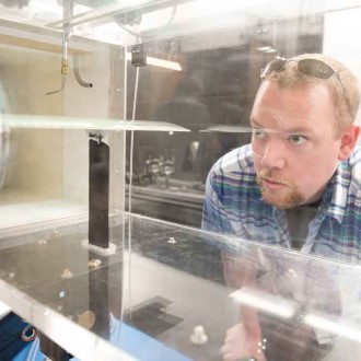
Wind Tunnel Lab
In the Wind Tunnel Lab students explore several aspects of the fluid flow, including forces acting on the body exposed to the air flow. With flow visualization techniques, students can also observe the streamlines. They measure drag and lift forces for variously shaped bodies.
Wind Tunnel Lab Collapse
The laboratory contains a wind tunnel with 1 ft x 1ft cross section and maximum velocity of 150 ft/s, a small calibration wind tunnel, and a small Schlieren system. Flow visualization in a wind tunnel is accomplished using a transversing laser sheet.